
Flying wings, Coanda jets, and active control: how Active Flow Control replaces control surfaces, from the 6DoF model to the DEMON and D90 demonstrators.
Summary
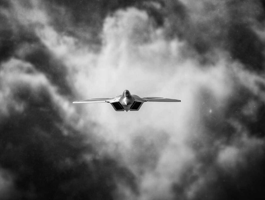
Tail-less aircraft gain in drag and stealth, but lose stability and control margins, especially in yaw. Active flow control (AFC) aims to restore this authority by blowing jets of air at the trailing edge or near the nose. By exploiting the Coanda effect, these jets modify the flow around the wing, and thus the lift, drag, and moments. The Dihedral-90 (D90-v2) demonstrator, a flying wing with a wingspan of 2.29 m and weighing 36.3 kg, draws up to 15% of the air from the compressor to feed the Coanda effectors. The measurements give derivatives comparable to those of DEMON, with a lift sensitivity of around 20 for a blow coefficient Cµ between 0.001 and 0.003. The pressurization dynamics impose a delay of approximately 0.055 s. The challenge then becomes a system engineering problem: modeling, estimating, and allocating nonlinear control in a robust loop. Within the flight envelope.
The challenge of tailless aircraft
Aerodynamic and discrete gains
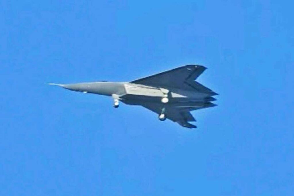
A tailless configuration is not a designer’s whim. A vertical tail and a horizontal plane are effective… but they come at a cost. They add wet surface area, joints, discontinuities, and therefore parasitic drag. They also create edges and volumes that can complicate the radar signature. A well-designed flying wing promises the opposite: less drag, less structural mass dedicated to the tail, and internal volume that can be used for fuel or equipment.
This reasoning is particularly tempting for fast drones or future fighter jets, where a compromise between endurance, speed, and stealth is sought. The problem is that the tail is not just a “penalty.” It is a lever of stability and control authority. Remove it, and you end up with a more difficult equation to solve.
The price to pay in stability and control
Without a fin, yaw damping and directional stability plummet. Without a horizontal plane, static pitch margin is managed with profiles, twists, centers of gravity, and elevons that are constantly battling between lift and trim. At high angles of attack, nonlinear phenomena (local stalls, separation, vortices) occur earlier and more abruptly.
If moving surfaces become a handicap (drag, signature, complexity), can we “fly” an aircraft without moving anything, simply by manipulating the air?
The physical logic of active flow control
The basic idea
Active control does not seek to overcome aerodynamics. It diverts it. Instead of deforming a control surface to impose a local angle of attack variation, energy is injected into the boundary layer or the nearby flow. The objective is to cause, delay, or shift a separation, change the effective circulation around a trailing edge, or generate a lateral force.
The consequence is crucial: the actuator is no longer a servo that moves a surface, but a chain of “air intake → valves → plenums → nozzles.” This transforms a mechanical problem into a coupled aerodynamic-pneumatic-control problem.
The role of the Coanda effect
The principle most exploited here is the Coanda effect: a jet of air tends to “stick” to an adjacent curved surface. If the jet is blown in the right place, it follows the curvature and drives the surrounding flow. This makes it possible to curve the wake, increase circulation, and produce a moment, without hinges or flaps.
This is the idea behind “Coanda surface” effectors: a small slot, a curved surface, and a controlled flow rate. The result is measured in aerodynamic derivatives: how much the lift, pitch moment, roll, or yaw change when the airflow is increased.
The key parameter Cµ
In this field, we don’t just talk about “flow rate.” We use a dimensionless parameter, the blow coefficient Cµ, which reduces the jet to a fraction of the dynamic pressure and a reference surface. This language allows us to compare aircraft sizes, speeds, and effector architectures.
In the case of the D90-v2, the simulations and tests reported show that, for a range of 0.001 ≤ Cµ ≤ 0.003, the sensitivity of lift to Cµ is of the order of 20 (dimensionless), with notable effects also in moment and roll. In other words, “small” Cµ values can already produce measurable variations, but they must be maintained with precision and repeated at high frequency for closed-loop control.
AFC effectors replacing control surfaces
Circulation control at the trailing edge
The heart of the device is a circulation control logic: blowing near the trailing edge to increase (or reduce) circulation and therefore local lift. By controlling the left/right zones separately, roll is created; by combining the front/rear zones (or up/down configurations), pitch is controlled.
The D90-v2 uses TECC (Trailing Edge Coanda Control) type trailing edge effectors and “split” variants. These choices are not aesthetic: they influence the range of authority, the linearity of the response, and the sensitivity to variations in local Mach number and angle of attack.
Blowing near the apex and side jets
On a flying wing, part of the lateral-directional stability is played out at the front: vortex, separation, asymmetries. The document also describes effectors near the apex (nose/leading edge area) that can influence the overall flow. On paper, this opens a door: regaining control when the rear effectors are saturated, or when the aircraft approaches areas of angle of attack where the trailing edge no longer has “grip.”
But this is also where non-linearities come into play: the effectiveness of a jet can change abruptly depending on the state of separation. In terms of control, this translates into variable gains, and therefore a need to estimate or sequence control laws.
Fluidic thrust vectoring
British demonstrators have also explored a complementary approach: using secondary jets to deflect the propulsion plume. This is a way of generating yaw or pitch even if the flow over the wing becomes unfavorable. On MAGMA, this logic is explicitly presented as “fluidic thrust vectoring,” tested in parallel with circulation control.
This approach is appealing… and it has an obvious downside: it affects propulsion, and therefore thermal performance, compressor margins, loss of available thrust, and constraints on the nozzle.
The flight control chain when the actuator is air
The model and estimation
An aircraft is typically flown using a nested loop architecture: rate loop (p, q, r), then attitude loop (φ, θ, ψ), then trajectory loop. This document follows this approach, but with one nuance: the AFC actuator has its own dynamics. The pressure in a plenum does not instantly follow a valve setpoint. There is a gain, a time constant, and above all a delay.
On the D90-v2, the relationship between Valve 1 control and plenum pressure is modeled by a first-order transfer function with a delay of approximately 0.055 s and a time constant of approximately 0.073 s. In aeronautics, 55 ms may seem small.
In flight control, it is enough to degrade a rate loop if it is not compensated for.
Control allocation and its constraints
As soon as there are several effectors, the question is no longer “how much force to produce?” but “how to distribute it?” This is the role of command allocation: to solve a problem under constraints (pressure limits, maximum flow rate, valve opening rate) to obtain the required roll, pitch, and yaw.
The difficulty is twofold. First, the effectors are not orthogonal: a TECC can produce roll and pitch simultaneously. Second, efficiency depends on speed and flow conditions. The document proposes derivative matrices and allocation strategies that remain usable in real time, while recognizing this key point: AFC transforms an aircraft into a multi-physical system, and the algorithm must “live” with uncertainty.
Actuation dynamics and delays
With a control surface, the delay comes mainly from the servo and surface inertia. With AFC, it comes from air volumes, pressure losses, compressibilities, valves, and the source (bleed).
The D90-v2 provides a very concrete constraint: the Hawk 270R turbojet engine cannot provide unlimited bleed. The document mentions up to 15% of compressor air available, but specifies that sustained extraction beyond approximately 10% can cause engine flameout. This is a “hard” limit. It dictates the strategy: AFC can be very authoritative, but it must be managed as a scarce resource, especially during prolonged maneuvers.
Demonstrators that put theory to the test
The DEMON case
The DEMON demonstrator, developed with BAE Systems and universities including Cranfield University, marked a symbolic milestone: a flapless flight authorized by the UK Civil Aviation Authority in September 2010. The figures are useful because they bring the technology down to a real-world scale: approximately 90 kg, 2.5 m wingspan, and an architecture designed to switch from conventional control to fluidic control.
What makes DEMON valuable is not a marketing promise. It is a fact: blast control can stabilize and maneuver an entire vehicle in a real environment, with its gusts, dispersions, and uncertainties.
The MAGMA case
MAGMA extends the idea with two building blocks: trailing edge circulation control and fluidic thrust vectoring. The message is clear: reducing moving surfaces can reduce signature and maintenance, but the technology must demonstrate sufficient power density. Public statements from the University of Manchester and BAE emphasize high-energy jets capable of replacing visible flaps with slits that are virtually invisible from a distance.
The industrial background is also understandable: AFC is not just a “stealth” option. It is a fleet sustainability option, as it reduces moving parts, inspections, and mechanical failures.
The X-65 case in the CRANE program
The move to the next level is embodied by DARPA’s CRANE program, with Aurora Flight Sciences (Boeing group) building the X-65. The stated ambition is straightforward: to demonstrate AFC actuators as the primary means of control on an airframe without conventional external control surfaces.
This is a strategic milestone because it forces the resolution of difficult issues: robustness in disturbed environments, valve redundancy, fault tolerance, and validation of control laws over a wider flight envelope than that of small demonstrators.
Industrial and operational compromises
Energy penalty and propulsive efficiency
Let’s be blunt: AFC costs energy. Taking bleed air from a compressor reduces the air available for the combustion chamber and alters the engine’s operating margins. The document highlights a harsh reality for D90-v2: bleed must be limited to avoid engine failure. This constraint turns AFC into a “budget” resource. During cruise, it can be economical. During maneuvers, it can consume energy quickly.
This pushes toward hybrid architectures: AFC for phases where discretion, drag, or signature matter most, and minimal surfaces (or micro-surfaces) as a backup, or for prolonged maneuvers.
Mass, volume, and maintenance
We often imagine that “no control surfaces” means “lighter.” The document provides some nuance. On D90-v2, the dedicated appendix compares a conventional control surface system (servos, linkages) and an AFC system (valves, plenum, tubing). The interesting result is that the AFC can be more compact in total volume (approximately 3.6×10⁻³ m³ versus 8.9×10⁻³ m³), but slightly heavier (approximately 2.18 kg versus 1.71 kg), depending on the configuration studied.
This is not a contradiction. Control surfaces take up space but remain relatively simple. AFC shifts the complexity to “system” components: piping, instrumentation, sealing, thermal performance. Maintenance changes in nature: fewer hinges, more pneumatics and sensors.
Certification and operational safety
Replacing a control surface with a jet also means replacing a mechanical failure with a flow failure. A stuck valve, a leak, a faulty pressure sensor, contamination, and control authority can be lost. Certification will therefore require redundancies, reconfiguration strategies, and demonstrations of degraded effectiveness.
Added to this is a point that is rarely discussed: AFC “imprints” a control noise in the flow (pulsed jets, blast). On a military aircraft, this is not necessarily critical. On a civil aircraft, it can become an issue of comfort, structural fatigue, or the environment.
The credible trajectory of a technology that aims to replace the tail
The promise of AFC on tailless aircraft is real: control without moving surfaces, greater integration, and potentially greater discretion. The document also shows that reality is more demanding: a control surface cannot be replaced by an idea, but by a complete chain, with its delays, saturations, and engine constraints. If we want these architectures to move from the laboratory to the operational fleet, we will have to treat AFC as a “vital organ”: modeled, diagnosed, redundant, and managed as an energy resource. At this price, the flying wing ceases to be an aesthetic gamble and becomes what it has always been: an engineering solution, but one that can finally be flown without easy compromises.
Sources
- Sai Simon, “Flight Control of Tailless Aircraft with Active Flow Control”, University of Cincinnati, 2025.
- BAE Systems, “DEMON UAV – Flying Without Flaps”.
- BAE Systems, “MAGMA: the future of flight”.
- DARPA, “DARPA Moves Forward on X-65 Technology Demonstrator”.
- Aurora Flight Sciences, “Revolutionary X-Plane Takes Shape” (X-65).
- NATO Science and Technology Organization, AVT-239, “Innovative Control Effectors for Manoeuvring of Air Vehicles”.
War Wings Daily is an independant magazine.